| 首页 | 高清影视 | 网上日记 | 致富经 | 展会 | 音乐生活 | 网址导航 | 在线游戏 | 网站建设 | 会员中心 | 注册 | 更多功能 |


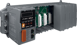
 iP-8000-MTCP series is a Modbus TCP I/O expansion unit to expand I-8K and I-87K series I/O modules over the Ethernet for industrial monitoring and controlling applications. There are more than 50 I/O modules supported with the unit, including analog input/output, digital input/output, counter, frequency I/O modules. It is designed to be used in harsh and noisy environment, so the hardware is manufactured with wide power input range (10 ~ 30 VDC), isolated power input and can operate under wide temperature (-25 ~ +75°C). To simplify installation and maintenance of I/O modules, it provides many useful features, such as: auto configuration, LED indicators for fault detection, dual watchdog to keep alive, programmable power on and safe values for safety. Modbus is a very wide known protocol in the industrial manufacturing and environment monitoring fields. Many SCADA software, HMI and PLC has builtin driver to support Modbus devices. Besides, we also provide SDK on different platforms, such as Windows XP, Window CE 5.0/6.0, Linux, MiniOS7. Therefore, it is very easy to integrate remote I/O to customer’s applications. Further more, the iP-8000-MTCP is also a c language based programmable controller that equipped a DOS-like OS (MiniOS7). Programmers can use C compilers that can create 16 bit executable file (*.exe) to customize the Modbus firmware which preinstalled in the iP-8000-MTCP. The SDK provides rich functions for Modbus communication, such as Modbus TCP master/slave, Modbus RTU master/salve, Modbus ASCII master/slave, etc. | |||
|
| Models | iP-8441-MTCP | iP-8841-MTCP |
| System Software | ||
| OS | MiniOS7 (DOS-like embedded operating system) | |
| Program Download Interface | RS-232 (COM1) or Ethernet | |
| Flash | C language | |
| Compilers to create.exe Files | TC++ 1.01 TC 2.01 BC++3.1 ~ 5.2x MSC 6.0 MSVC++ (before version 1.5.2) | |
| CPU Module | ||
| CPU | 80186 or compatible (16-bit and 80 MHz) | |
| SRAM | 768 KB | |
| Flash | 512 KB (100,000 erase/write cycles) with Flash protection switch | |
| Expansion Flash Memory | microSD socket (can support 1/2 GB microSD) | |
| Dual Battery Backup SRAM | 512 KB; data valid up to 5 years | |
| EEPROM | 16 KB | |
| NVRAM | 31 bytes (battery backup, data valid up to 5 years) | |
| RTC (Real Time Clock) | Provide second, minute, hour, date, day of week, month, year | |
| 64-bit Hardware Serial Number | Yes, for Software Copy Protection | |
| Watchdog Timers | Yes (0.8 second) | |
| NET ID | 8-pin DIP switch to assign NET ID as 1 ~ 255 | |
| Communication Ports | ||
| Protocol | Modbus TCP Slave | |
| Modbus RTU/ASCII Slave | ||
| Modbus TCP to RTU Gateway | ||
| Ethernet | RJ-45 x 2, 10/100 Base-TX (Auto negotiating, Auto MDI/MDI-X, LED indicators) | |
| COM 0 | Internal communication with the high profi le I-87K series modules in slots | |
| COM 1 | RS-232 (to update firmware) (RxD, TxD and GND); non-isolated | |
| COM 2 | RS-485 (D2+, D2-; self-tuner ASIC inside); 3000 VDC Isolation | |
| COM 3 | RS-232/RS-485 (RxD, TxD, CTS, RTS and GND for RS-232, Data+ and Data- for RS-485); non-isolated | |
| COM 4 | RS-232 (RxD, TxD, CTS, RTS, DSR, DTR, CD, RI and GND); non-isolated | |
| SMMI | ||
| LED Display | Yes, 5-Digit | |
| Programmable LED Indicators | 3 | |
| Push Buttons | 4 | |
| Buzzer | Yes | |
| I/O Expansion Slots | ||
| Slot Number | 4 | 8 |
| Note: For High Profi le I-8K and I-87K Modules Only | ||
| Data Bus | 8/16 bits | |
| Address Bus Range | 2 K for each slot | |
| Mechanical | ||
| Dimensions (W x L x H) | 231 mm x 132 mm x 111 mm | 355 mm x 132 mm x 111 mm |
| Installation | DIN-Rail or Wall Mounting | |
| Environmental | ||
| Operating Temperature | -25 ~ +75 °C | |
| Installation | -30 ~ +80 °C | |
| Ambient Relative Humidity | 10 ~ 90% RH (non-condensing) | |
| Power | ||
| Input Range | +10 ~ +30 VDC | |
| Isolation | 1 kV | |
| Redundant Power Inputs | Yes, with one power relay (1 A @ 24 VDC) for alarm | |
| Capacity | 30 W | |
| Consumption | 6.7 W | 7.2 W |
